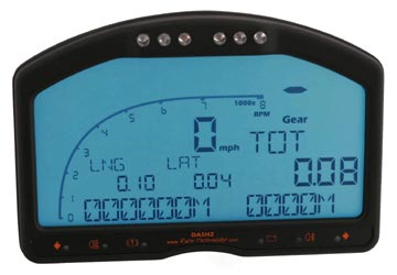
~ Race Technology Dash 2 Installation ~
The Race Technology Dash 2 Technical information and fitting guide for a Westfield.
This article was written by "Frosty" from the WSC.
 Owing to an increasing number of questions in the forums, I thought an article was needed as a central store for information relating to the Race Technology DASH2 Digital Dashboard
Hopefully this will clear up a lot of the questions regarding installation problems and configurations that people have been having with this Digi Dash.
Westfield Sportscars now supply these as a standard fitment and although they have been configured to "work out of the box", people are still having problems with the installation.
If you think any of this information is incorrect or could benefit from more updates, please let me know and I will ask Frosty to update it for me. I will then post up the changes.
I keep reading about pull-up resistors - what are they and why do I need them ?
The DASH2 is capable of reading sensor values for things like fuel level, oil pressure, and engine temperature etc. For each of these sensors, the DASH2 expects a mapped voltage input for given values. e.g. 100c = 2.54V. The problem is, Westfield supply VDO sensors with their kits which give varying resistance instead of varying voltage to indicate values.
This is no problem though, because the Westfield loom that is supplied with the DASH2 has 4 neat little circuits (potential dividers - one per sensor channel) which already contains the pull-up resistor. All you need to do is connect the sensor to the loom as per the instructions.
What are the pull-up resistors rated at ?
The pull-up resistors are 910 ohms each. This is the basis of your calculations to convert resistance to voltage (more on this later).
Which sensors are connected to which input ?
On the Westfield DASH2 loom they are as follows:
Analog 1: Not used (but circuit is there ready for a connection for a sensor of your own).
Analog 2: Water temp
Analog 3: Fuel level
Analog 4: Oil pressure
Ok, my DASH2 is plugged in, sensors are all connected, so how do I configure them ?
The DASH2 will now see a voltage from each of the sensors that you have plugged in, and you need to tell the DASH2 what these voltages mean. We'll start with the fuel sender...
- Download the Race Technology software from their website, install, and then open DASH2 software.
- On the input scaling tab, select "Analog 3" from the dropdown list - this is the analog input connected to the fuel level sender in our loom.
- Select "Generate an equation from table" and you will see a new window. This window references voltage to a value. So if you put in 1.0 as the voltage, and 50 as the value, the fuel level would display "50" when there is 1.0V from the fuel tank sender. So you add the full voltage as 100, and the empty voltage as 0. Pretty simple huh? (Details on how to find these voltages follow below...)
- Name the channel - this is what will appear on the DASH2 display whilst driving. "Fuel" will do in this case.
- Save your configuration file, and then send it to the DASH2 unit.
How do I calculate the voltage values from the resistance that the sensors output?
It might help to read up here on how a potential divider works to help you understand what's going on.
This site is very easy to understand: Electronics 2000 - Pot Divider
If you do not care though, then all you need are 3 things. The voltage of the circuit (this is always exactly 5V because each of the circuits are powered from the DASH2 regulated 5v reference feed), the fixed pull-up resistor value (910 ohms - see above), and the resistance from the sensor you are calibrating.
The calculation is as follows: Voltage = (Sensor_ohms / (910 + Sensor_ohms)) * 5v
As a sample, let's do the fuel sender at empty (3 ohms) and full (180 ohms).
So the voltage the fuel sensor will output at 3 ohms = (3ohms / (910 + 3 ohms)) * 5 = 0.016429V
Now full fuel (180 ohms) = (180ohms / (910 + 180ohms)) * 5 = 0.825688
Hopefully this has explained exactly how the potential divider is used, and how to calculate voltage from sensor resistance for various values. An Excel spreadsheet will save you masses of time here.
What are the resistance values for each of the VDO sensors?
The data can be found in the following PDF's.
Temperature Sensors:
vdo_temp_sensors.pdf
Water temp (marked 801/5/1) = curve table 92-027-004.
Oil temp (marked 801/9/3) = curve table 92-027-006.
Pressure Sensors:
vdo_pressure_sensors.pdf
Fuel Level Sensors:
3 ohms = empty
180 ohms = full
Is there a Spreadsheet I can use for easy calibration and pasting into the DASH2 software?
You can either write one yourself, or just download the one I created which has full resistance values for oil pressure, oil temperature, fuel level, and water temperature, as well as the ability to specify different pull-up resistor and reference feed values. This will save you a lot of typing
Download the spreadsheet here: vdo_sensors.xls
Speedo sensor Issues:
If you have upgraded to the DASH2 after building your car, the chances are you have a VDO speedo transducer at the rear of your car working from the 6 driveshaft bolts. Unfortunately, this sensor is NOT compatible with the DASH2 (something to do with the sensor frequency). Westfield supply a slightly different sensor which works using the front wheel hub bolts instead.
The sensor is available from Westfield, or from RS Components. The part number is XS1N08PA349. It's around £40 for the unit.
Speedo Sensor Wiring:
If you have the Westfield loom for the DASH2 then you need to find the speedo block connector, and then solder the 3 speedo sensor wires into this block in the following way:
| Sender | Speedo Loom | |
| BROWN | --> | GREEN (+12v) |
| BLUE | --> | BLACK (GND) |
| BLACK | --> | YELLOW/WHITE (Pulse signal) |
All you are doing here is re-routing the wires that would normally plug into the speedo unit, and instead using them to power the sensor, and then return the pulse to the block connector.
If you do not have the Westfield loom, you need to use any 12v signal that is live with ignition (nearly always a green cable), and use this to power the sensor (brown cable as above). You must also earth the sensor (blue cable).
Lastly, you need to return the pulse signal to the DASH2. All you need to do here is connect the black cable from the sensor to the brown wire that goes into the DASH2 unit on the CONN1 block. See your DASH2 manual if you are not sure where to find this.
This connects the speedo pulse from your sensor directly into the DASH2 speedo input.
JOB DONE!