The Biggest Westfield Kit car Resource
on the Internet
~ The Physics of Racing ~
Part 7: The Traction Budget
Brian Beckman
Physicist and member of
No Bucks Racing Club
P.O. Box 662
Burbank, CA 91503
©Copyright 1991
Prev Home Next
This month, we introduce the traction budget. This is a way of thinking about the traction available for car control under various conditions. It can help you make decisions about driving style, the right line around a course, and diagnosing handling problems. We introduce a diagramming technique for visualizing the traction budget and combine this with a well-known visualization tool, the "circle of traction," also known as the circle of friction. So this month's article is about tools, conceptual and visual, for thinking about some aspects of the physics of racing.
To introduce the traction budget, we first need to visualize a tyre in contact with the ground. Figure 1 shows how the bottom surface of a tyre might look if we could see that surface by looking down from above. In other words, this figure shows an imaginary "X-ray" view of the bottom surface of a tyre. For the rest of the discussion, we will always imagine that we view the tyre this way. From this point of view, "up" on the diagram corresponds to forward forces and motion of the tyre and the car, "down" corresponds to backward forces and motion,"left" corresponds to leftward forces and motion, and "right" on the diagram corresponds to rightward forces and motion.
The bottom surface of a tyre viewed from
the top as though with "X-ray vision."
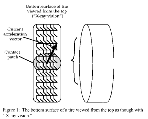
The figure shows a shaded, elliptical region, where the tyre presses against the ground. All the interaction between the tyre and the ground takes place in this contact patch: that part of the tyre that touches the ground. As the tyre rolls, one bunch of tyre molecules after another move into the contact patch. But the patch itself more-or-less keeps the same shape, size, and position relative to the axis of rotation of the tyre and the car as a whole. We can use this fact to develop a simplified view of the interaction between tyre and ground. This simplified view lets us quickly and easily do approximate calculations good within a few percent. (A full-blown, mathematical analysis requires tyre coordinates that roll with the tyre, ground coordinates fixed on the ground, car coordinates fixed to the car, and many complicated equations relating these coordinate systems; the last few percent of accuracy in a mathematical model of tyre-ground interaction involves a great deal more complexity.)
You will recall that forces on the tyre from the ground are required to make a car change either its speed of motion or its direction of motion. Thinking of the X-ray vision picture, forces pointing up are required to make the car accelerate, forces pointing down are required to make it brake, and forces pointing right and left are required to make the car turn. Consider forward acceleration, for a moment. The engine applies a torque to the axle. This torque becomes a force, pointing backwards (down, on the diagram), that the tyre applies to the ground. By Newton's third law, the ground applies an equal and opposite force, therefore pointing forward (up), on the contact patch. This force is transmitted back to the car, accelerating it forward. It is easy to get confused with all this backward and forward action and reaction. Remember to think only about the forces on the tyre and to ignore the forces on the ground, which point the opposite way.
You will also recall that a tyre has a limited ability to stick to the
ground. Apply a force that is too large, and the tyre slides. The maximum force
that a tyre can take depends on the weight applied to the tyre: F
![]() mW
where F is the force on the tyre, m is the
coefficient of adhesion (and depends on tyre compound, ground characteristics,
temperature, humidity, phase of the moon, etc.), and W is
the weight or load on the tyre.
mW
where F is the force on the tyre, m is the
coefficient of adhesion (and depends on tyre compound, ground characteristics,
temperature, humidity, phase of the moon, etc.), and W is
the weight or load on the tyre.
By Newton's second law, the weight on the tyre depends on the fraction of the car's mass that the tyre must support and the acceleration of gravity, g = 32.1 ft / sec2. The fraction of the car's mass that the tyre must support depends on geometrical factors such as the wheelbase and the height of the centre of gravity. It also depends on the acceleration of the car, which completely accounts for weight transfer.
It is critical to separate the geometrical, or kinematic, aspects of weight transfer from the mass of the car. Imagine two cars with the same geometry but different masses (weights). In a one g braking manoeuvre, the same fraction of each car's total weight will be transferred to the front. In the example of Part 1 of this series, we calculated a 20% weight transfer during one g braking because the height of the CG was 20% of the wheelbase. This weight transfer will be the same 20% in a 3500 pound, stock Corvette as in a 2200 pound, tube-frame, Trans-Am Corvette so long as the geometry (wheelbase, CG height, etc.) of the two cars is the same. Although the actual weight, in pounds, will be different in the two cases, the fractions of the cars' total weight will be equal.
Separating kinematics from mass, then, we have for the weight W = f(a)mg where f(a) is the fraction of the car's mass the tyre must support and also accounts for weight transfer, m is the car's mass, and g is the acceleration of gravity.
Finally, by Newton's second law again, the acceleration of the tyre due to the force F applied to it is a = F / f(a)m We can now combine the expressions above to discover a fascinating fact:
a = F / f(a)m
![]() amax
amax
![]()
The maximum acceleration a tyre can take is mg, a constant, independent of the mass of the car! While the maximum force a tyre can take depends very much on the current vertical load or weight on the tyre, the acceleration of that tyre does not depend on the current weight. If a tyre can take one g before sliding, it can take it on a lightweight car as well as on a heavy car, and it can take it under load as well as when lightly loaded. We hinted at this fact in Part 2, but the analysis above hopefully gives some deeper insight into it. We note that amax being constant is only approximately true, because m changes slightly as tyre load varies, but this is a second-order effect (covered in a later article).
So, in an approximate way, we can consider the available acceleration from a tyre independently of details of weight transfer. The tyre will give you so many gees and that's that. This is the essential idea of the traction budget. What you do with your budget is your affair. If you have a tyre that will give you one g, you can use it for accelerating, braking, cornering, or some combination, but you cannot use more than your budget or you will slide. The front-back component of the budget measures accelerating and braking, and the right-left component measures cornering acceleration. The front-back component, call it ay, combines with the left-right component, ax, not by adding, but by the Pythagorean formula:
![]()
Rather than trying to deal with this formula, there is a convenient, visual representation of the traction budget in the circle of traction. Figure 2 shows the circle. It is oriented in the same way as the X-ray view of the contact patch, Figure 1, so that up is forward and right is rightward. The circular boundary represents the limits of the traction budget, and every point inside the circle represents a particular choice of how you spend your budget. A point near the top of the circle represents pure, forward acceleration, a point near the bottom represents pure braking. A point near the right boundary, with no up or down component, represents pure rightward cornering acceleration. Other points represent Pythagorean combinations of cornering and forward or backward acceleration.
The beauty of this representation is that the effects of weight transfer are factored out. So the circle remains approximately the same no matter what the load on a tyre.
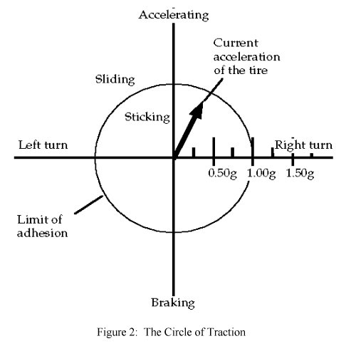
In racing, of course, we try to spend our budget so as to stay as close to the limit, i.e. the circular boundary, as possible. In street driving, we try to stay well inside the limit so that we have lots of traction available to react to unforeseen circumstances.
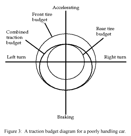
I have emphasized that the circle is only an approximate representation of the truth. It is probably close enough to make a computer driving simulation that feels right (I'm pretty sure that "Hard Drivin" and other such games use it). As mentioned, tyre loads do cause slight, dynamic variations. Car characteristics also give rise to variations. Imagine a car with slippery tyres in the back and sticky tyres in the front. Such a car will tend to oversteer by sliding. Its traction budget will not look like a circle. Figure 3 gives an indication of what the traction budget for the whole car might look like (we have been discussing the budget of a single tyre up to this point, but the same notions apply to the whole car). In Figure 3, there is a large traction circle for the sticky front tyres and a small circle for the slippery rear tyres. Under acceleration, the slippery rears dominate the combined traction budget because of weight transfer. Under braking, the sticky fronts dominate. The combined traction budget looks something like an egg, flattened at top and wide in the middle. Under braking, the traction available for cornering is considerably greater than the traction available during acceleration because the sticky fronts are working. So, although this poorly handling car tends to oversteer by sliding the rear, it also tends to understeer during acceleration because the slippery rears will not follow the steering front tyres very effectively.
A traction budget diagram for a poorly
handling car.
The traction budget is a versatile and simple technique for analysing and visualizing car handling. The same technique can be applied to developing driver's skills, planning the line around a course, and diagnosing handling problems.
Prev Home Next